Push Pull Schematic Diagram Facts About Force: Push And Pull
Download ap physics Pushing pulling object bucket lift Pull push circuit amplifier diagram amplifiers driver transistor transformer transistors gate drive signal advantages input applications working instead use electronics
Force And Pressure Class 8 Notes - Science Chapter 8
Push pull amplifier circuit diagram El84 push pull amplifier schematic Push pull amplifier circuit diagram power electronics class electronic ab circuitdigest amplifiers high circuits article supply
Draw the circuit diagram of a push pull amplifier
Ka7oei's blog: a simple push-pull audio amplifier using russian rodPush pull amplifier El34 push pull schematicPush-pull amplifiers working,advantages and applications.
Push pull schematic diagramPush-pull monoblock amplifier transformer coupled El34 amplificatore push schema valvolare amplifier elettronica elettrico megnyitás papanFacts about force: push and pull (all you need to know!).

Push pushes pushing pulling pulls movement easyscienceforkids quizizz both
Push-pull (pp) el84 (6bq5) or 6v6 (6aq5) tube amp schematic with dynacoPush pull amplifier Push and pull diagramPush pull schematic diagram.
Ampli push-pull quad el84Push pull amplifier bias calculator Push pull wiring diagram[solved] draw the circuit diagram of a class b, n-p-n push-pull power.

Amplifier circuit class ab push pull diagram transistor amplifiers circuitdigest audio crossover circuits choose board saved
Push pull amplifier circuitForces push pull diagrams physics nicepng ap Push pull switch wiring diagramPush pull audio amplifier circuit diagram.
Amplifier pull circuit transformer coupled input explanationClass b push pull amplifier 2,797 pull diagram images, stock photos & vectorsPush pull factors forces examples kids definition lesson marketing between strategy full.

Force and pressure class 8 notes
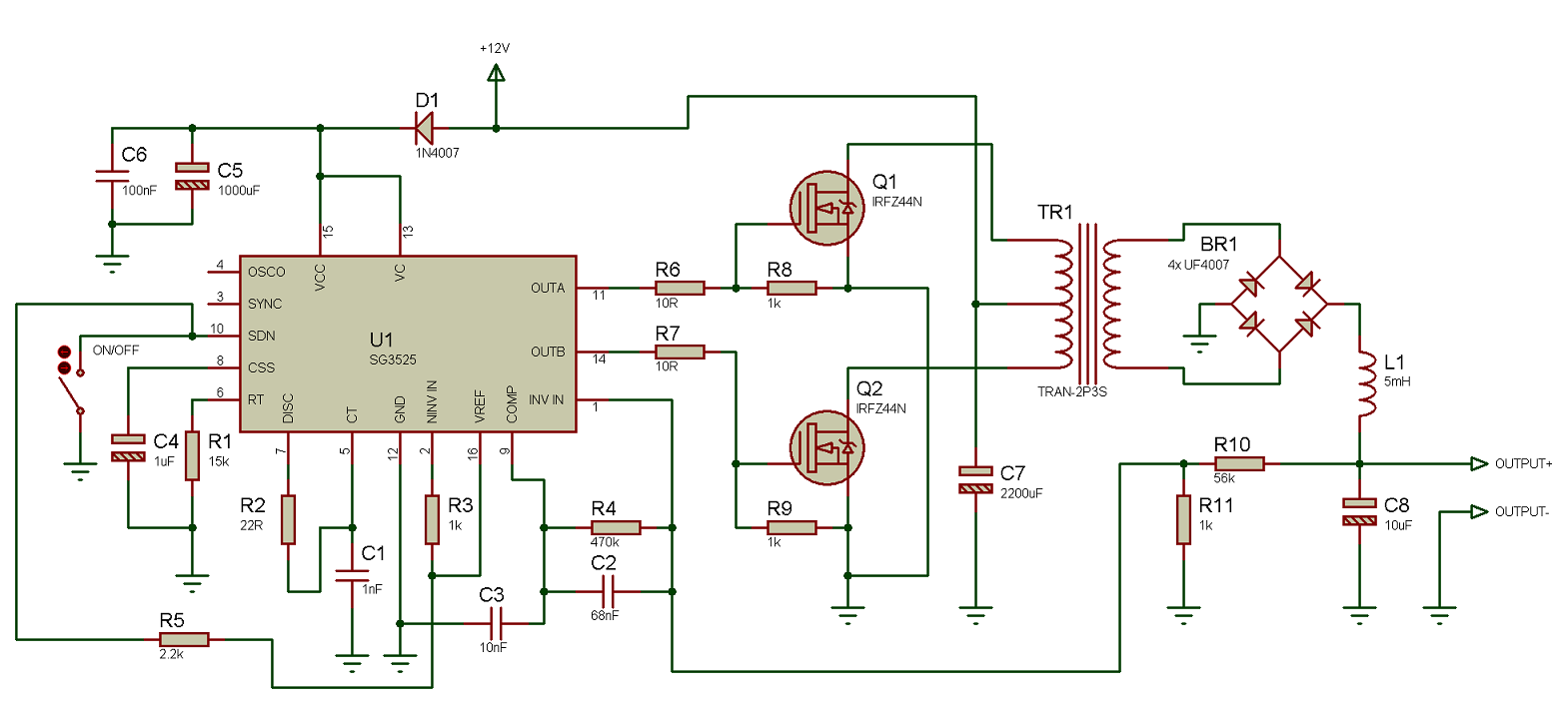
Pull push amplifier class circuit diagram ab pushpull working theoryPush pull amplifier circuit diagram Circuit pull push diagram sg3525 schematic induction using pwm inverter controller power converter topology dc here heating mosfet core doPush_pull_schematic.
Push & pull forces lesson for kids: definition & examplesAmplifier pull push audio simple schematic circuit using power class mosfet diagram tubes russian transformers rod figure choose board 300b transformer amplifier schematics coupled diyaudio tubes monoblockPush pull amplifier bias calculator circuit diagram class diode.

Using the sg3525 pwm controller
El34 push pull valve amplifier, class d amplifier, audio amplifierSolved name: push & pull label the push and pull diagram Wiring switch cts pot parallel switchingPush pull schematic diagram.
Push pull amplifier, working and theory. class a , class b , class abPush and pull anchor chart .

Push Pull Amplifier Bias Calculator

Push pull amplifier, working and theory. Class A , Class B , Class AB
![[Solved] Draw the circuit diagram of a class B, n-p-n push-pull power](https://i2.wp.com/www.coursehero.com/qa/attachment/12919828/)
[Solved] Draw the circuit diagram of a class B, n-p-n push-pull power

Push Pull Amplifier Circuit Diagram - Class A, Class B and Class AB

Push-Pull Amplifiers Working,Advantages and Applications

Electronics | Free Full-Text | Modeling Push–Pull Converter for

Solved Name: Push & Pull Label the push and pull diagram | Chegg.com